Olliter Manuals

PureSignal
This guide provides a practical overview of PureSignal setup and operation on OL-Master. It explains what PureSignal does, how to bring it up quickly, and how to interpret key indicators so you can achieve stable, repeatable transmit correction.
Note
Each transceiver might have different input and output levels for the PureSignal to work properly, please refer to the relevant user manual.
Note
Some power amplifier have a dedicated output to be used as PureSignal feedback, before connecting such cable to the Olliter SDR, please check the output level in the relevant manuals
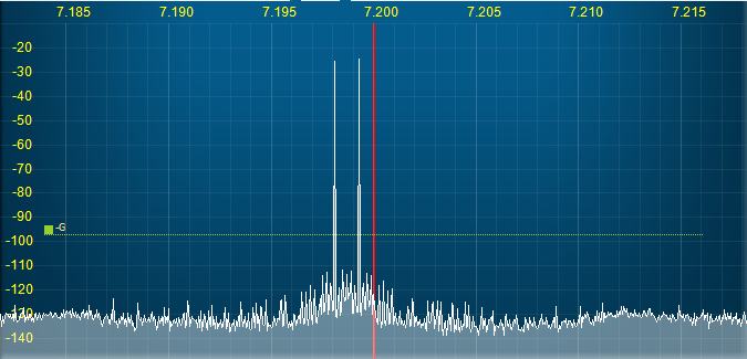
Table of contents
- What PureSignal does
- Requirements
- Before you start
- Quick-start workflow
- Detailed setup and controls
- Understanding Tint
- How to read the indicators
- AmpView (correction curve view)
- Typical operating patterns
- Troubleshooting
- Best practices
What PureSignal does
PureSignal is adaptive transmit predistortion.
In practical terms, it:
- Measures your TX output through a feedback path.
- Learns the non-linear behavior of your transmit chain.
- Applies correction so transmitted IMD products are reduced.
The result is usually a cleaner transmitted signal, especially when drive/compression are not excessive.
Requirements
- OL-Master configured and communicating normally with the radio.
- A valid PureSignal-capable feedback path in your station configuration.
- Stable TX chain during calibration and operation.
- Moderate transmit processing settings.
Before you start
- Keep TX processing moderate while setting up PureSignal.
- Avoid changing many TX parameters during active calibration.
- Start with normal speech or two-tone test as needed.
- Confirm RF power is set to a sane, repeatable level.
Note
PureSignal uses a fixed 192 kHz feedback path, and when spectrum width is increased, the overall DDC/network/DSP load rises. In some systems this can degrade feedback timing alignment and make PS behavior unstable. We recommend 96 kHz as the preferred transceiver bandwidth for stable PureSignal operation. Higher widths can work but are system-dependent.
Connecting PureSignal feedback with OL-SDR only
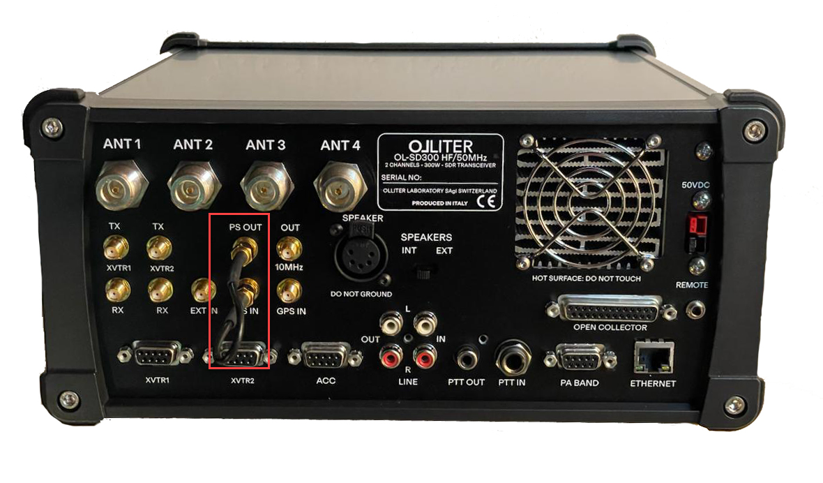
When using OL-SDR as the feedback path, connect the PS-OUT to the PS-IN of the OL-SDR using a short SMA to SMA cable. The PS-OUT is a buffered output that can drive the OL-SDR input without additional attenuation.
Connecting PureSignal feedback with external power amplifier
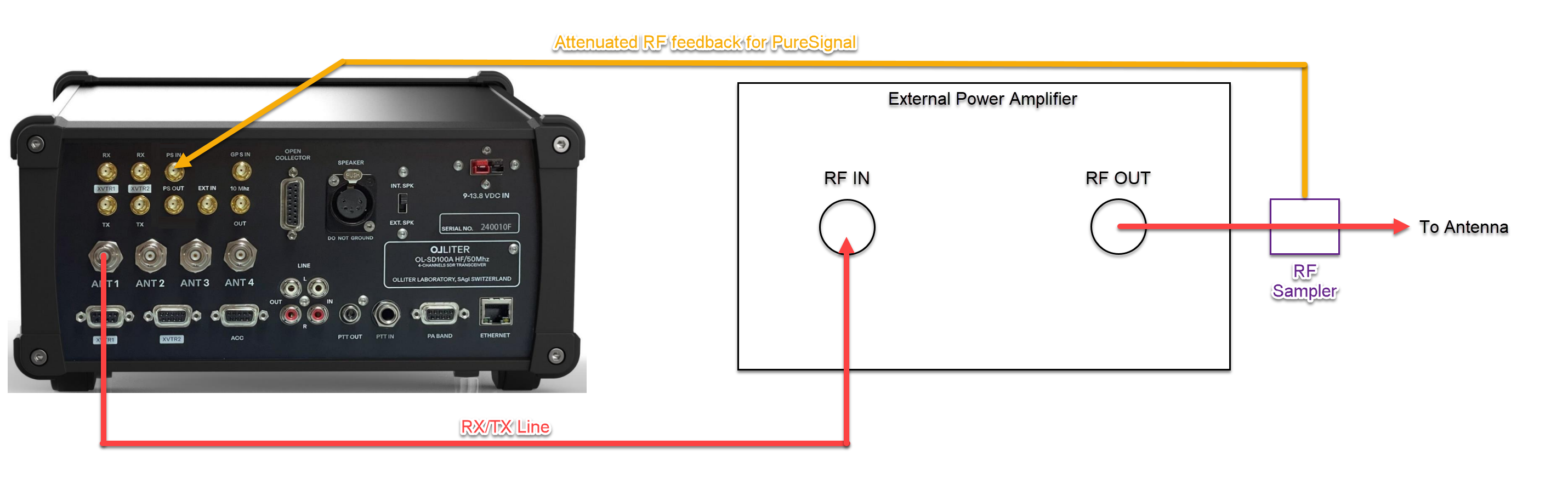
When using an external power amplifier, connect the attenuated amplifier output to the PS-IN of the OL-SDR. The amplifier should provide a suitable feedback signal to the OL-SDR input. Check both the OL-SDR and amplifier manuals for recommended feedback levels and connections.
Warning
Make sure the feedback signal from the amplifier is within the recommended range for the OL-SDR input to avoid damage or incorrect calibration.
Quick-start workflow
- Power on OL-Master and make sure normal TX/RX operation is stable.
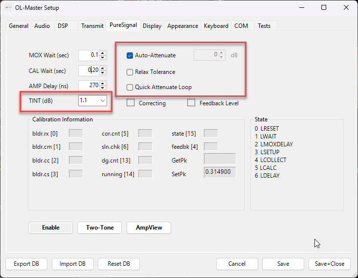
- Open Setup and go to the PureSignal section.
- Enable Auto-Attenuate.
- Keep Quick Attenuate Loop off for first setup.
- Set Enable for PureSignal (PS).
- Enter MOX and transmit with a stable signal.
- Watch feedback and correction indicators.
- Wait until indicators stabilize.
- Optionally open AmpView to inspect correction curves.
- Store your normal station profile once stable.
Detailed setup and controls
Master toggles
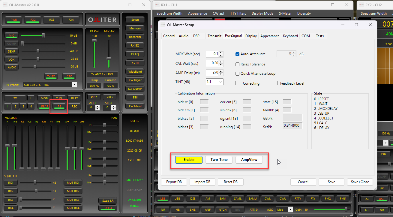
- PS: Main PureSignal on/off switch.
- Enable in Setup: mirrors the same PureSignal state.
- Two-Tone: useful when you want a repeatable calibration signal.
- AmpView: opens the correction/amplifier curve viewer.
Timing and calibration controls
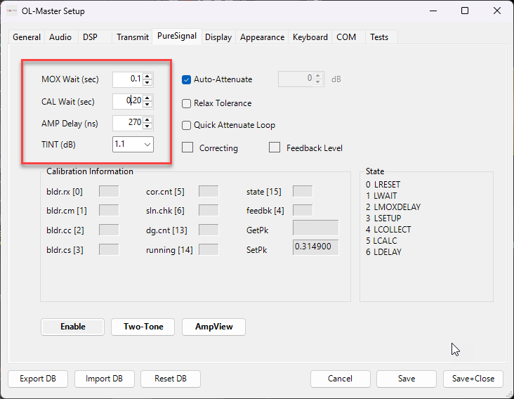
- MOX Delay: delay before calibration starts after TX is asserted.
- Cal Wait: wait between calibration cycles.
- Amp Delay: fine timing alignment between TX and feedback.
- Tint (0.5 / 1.1 / 2.5): selects internal calibration granularity presets.
Understanding Tint
Tint controls how PureSignal groups and updates correction data internally.
In operator terms, it is a tradeoff between:
- Responsiveness (how quickly correction adapts), and
- Smoothness/stability (how steady and low-noise the solution is).
What the three values generally mean
- 0.5: fastest adaptation.
- Best when you want quick lock and your feedback path is clean/stable.
- Can be more sensitive to noisy or changing conditions.
- 1.1: balanced mode.
- Good default for most stations.
- Usually the best starting point if you are unsure.
- 2.5: slowest but most averaged behavior.
- Useful when correction appears jumpy or inconsistent.
- Can improve stability at the cost of slower reaction.
When to change Tint
Try a different Tint if you see one or more of these:
- Feedback/correction indicators oscillate even after attenuation is settled.
- AmpView correction curves look unstable or noisy.
- Correction takes too long to become effective after entering MOX.
Practical tuning method
- Start with 1.1.
- Keep TX conditions constant (same power, same processing, same antenna path).
- Enter MOX and let PS settle.
- Observe indicators and, if needed, AmpView.
- If behavior is too nervous, try 2.5.
- If behavior is too slow but stable, try 0.5.
- Keep the setting that gives the most consistent result on your typical band/profile.
Important note
Tint is not a "more is better" setting. The best value depends on your station feedback path, band conditions, and operating style. Pick the value that gives repeatable, stable correction in real use.
Attenuation controls
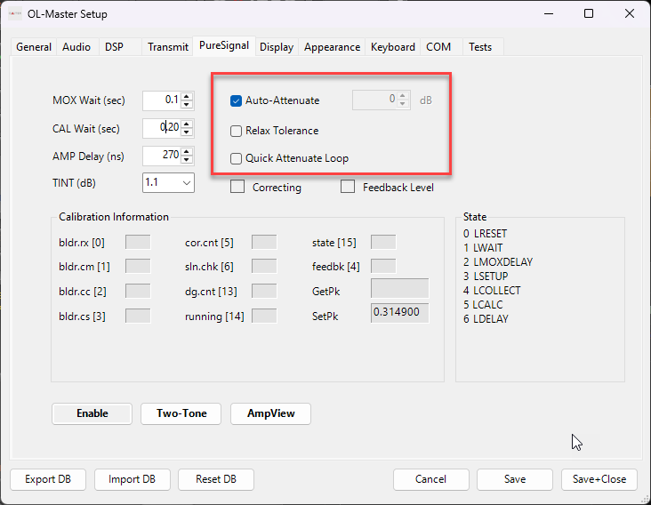
- Auto-Attenuate: automatically adjusts feedback attenuation toward a valid operating window.
- Quick Attenuate Loop: faster attenuation loop updates, useful after basic setup is known-good.
- PS Att: manual attenuation value (used when Auto-Attenuate is off).
Tolerance control
- Relax Tolerance: loosens correction tolerance, sometimes helpful in difficult feedback conditions.
How to read the indicators
PureSignal gives both numeric and visual feedback.
Visual status
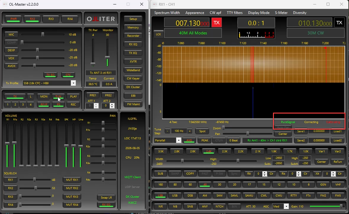
Two small colored indicators are key:
- Correcting: correction is being actively applied.
- Feedback Level: quality/level state of feedback seen by the engine.
On the main display, PS markers are also shown during active PS TX operation.
Color meaning (operational interpretation)
- Lime: target/good region.
- Yellow: marginal region.
- Red: poor or too low feedback.
- Blue: too high feedback.
These are not literal text labels like "good/ok/bad", but they serve that function visually.
Numeric fields
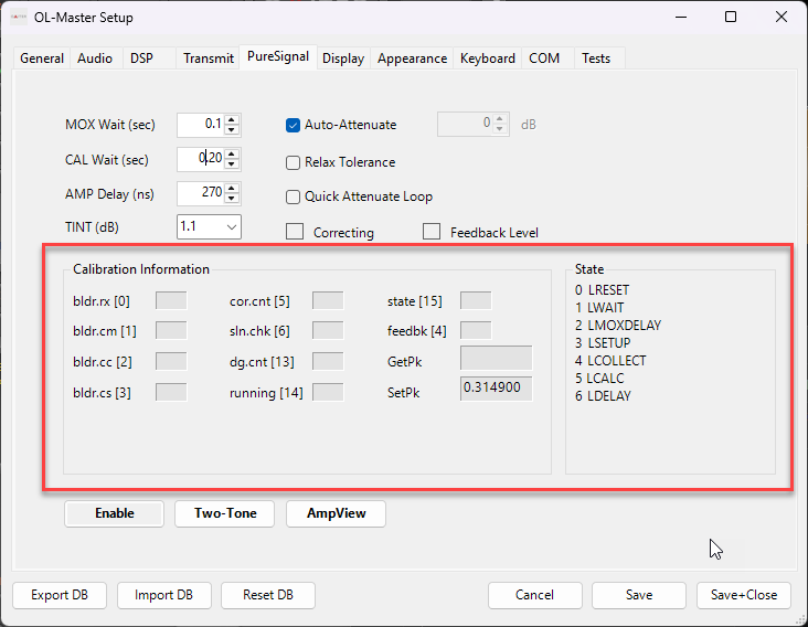
The calibration information group includes live telemetry such as:
- Feedback level.
- Correction counter.
- Running/correction-applied state.
- Engine state index.
- Peak-related values.
Use these for deeper diagnostics when visual status is unclear.
AmpView (correction curve view)
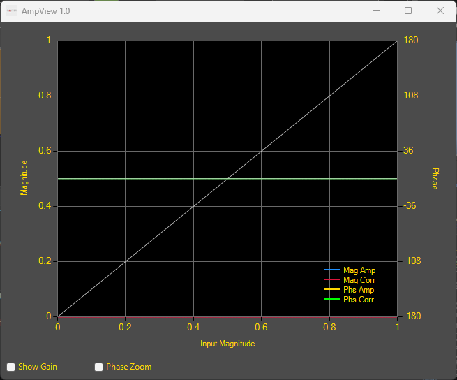
AmpView is the visual calibration/correction graph tool.
It displays:
- Mag Corr / Phs Corr: correction curves being applied.
- Mag Amp / Phs Amp: measured amplifier behavior.
Use AmpView when:
- You want to verify correction is smooth and stable.
- You are adjusting delays/tolerance and need visual confirmation.
- You are comparing behavior across profiles or bands.
Typical operating patterns
First-time setup
- Start with Auto-Attenuate on.
- Use a stable transmit condition.
- Wait for feedback indicator to settle in a good region.
- Confirm correction indicator is active.
- Validate on-air quality (or with external measurement).
Daily use
- Enable PS.
- Transmit normally.
- Briefly check indicators after entering MOX.
- If indicators remain healthy, operate as usual.
Profile or band change
- Re-check indicators after major profile/band changes.
- If behavior worsens, re-run a short stabilization cycle.
- Use AmpView only if quick checks do not explain behavior.
Troubleshooting
PS enabled but no visible correction
- Confirm you are in MOX.
- Confirm correction indicator activity.
- Check feedback level status color and numeric field.
- Verify feedback path/cabling/routing in your station setup.
Feedback always red or unstable
- Leave Auto-Attenuate enabled and allow it to settle.
- Reduce TX aggressiveness (compression/drive).
- Re-check delay values (MOX Delay, Amp Delay, Cal Wait).
- Ensure transmit signal is stable during calibration.
Feedback tends to blue (too high)
- Reduce feedback level via attenuation path.
- Re-check Auto-Attenuate behavior.
- Verify no sudden gain change was introduced in TX chain.
Works on one band but not another
- Re-check profile differences between bands.
- Run a short re-stabilization on the affected band.
- Compare AmpView behavior across bands if needed.
Unexpected behavior after many control changes
- Return to a known-good profile.
- Disable then re-enable PS.
- Re-enter MOX and allow a clean calibration cycle.
Best practices
- Keep TX chain settings predictable while using PS.
- Avoid excessive compression when targeting best linearity.
- Use Auto-Attenuate unless you have a specific manual reason.
- Use AmpView for diagnosis, not as a mandatory step every session.
- Re-validate quickly after major station configuration changes.